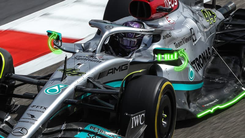
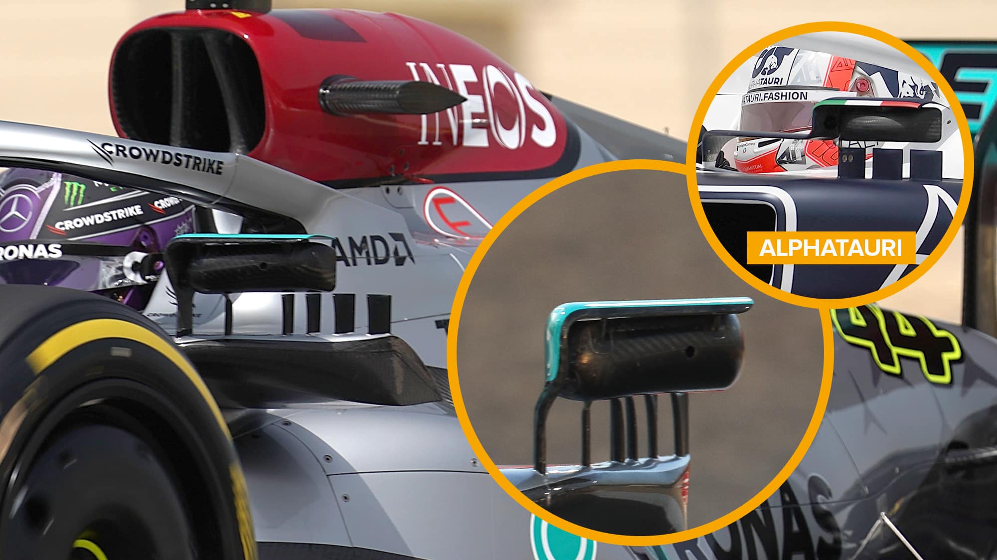
The outer winglets are using the ‘Mirror Rear Stay’ legality. This states that the stay ‘may’ be connected to the sidepod by this stay (it’s optional), and the stay has to fit within the width of the mirror body when viewed from the front. There are also rules on how far rearward it can go, and its maximum size in any plane. There are no rules on it regarding maximum number of sections in any plane, so having multiple winglets made from this (like AlphaTauri) is totally fine.
Just inboard though, there is an additional stay that transitions into a winglet over the top of the mirror. Now this stay is too far inboard to be part of the Mirror Rear Stay, and it violates the width ruling, so it must be defined as the ‘Mirror Inner Stay’.
The rules state that the ‘Mirror Inner Stay’ must connect the mirror body to the mid chassis, and lie inboard of the mirror body. There is also a limit on how low it can go, which is actually pretty low.
Crucially, you get to fully define the mirror stay prior to trimming it to the mid chassis and sidepod. This actually means you could define a mirror stay that passes through the sidepod geometry, originally connecting to the chassis, and then you can later trim it to the sidepod. Or to look at it the other way, if you extended the stay through, it would connect to the mid chassis. This is what I believe Mercedes is doing to justify their inboard mirror stay not coming all the way into the chassis.
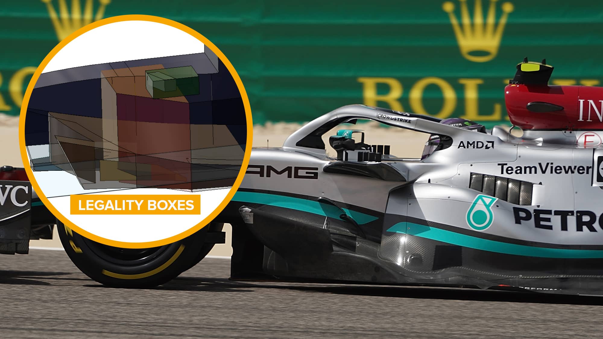
Now for the bodywork legality. Again Mercedes has been very clever in its interpretation of the rules here and this has allowed it to create a unique geometry compared to everyone else on the grid. It seems that all the action is happening within the bodywork that is declared as ‘sidepod’ (red legality box in image above). This bodywork can basically have as sharp a convex radius as you like, so long as it meets rules on concave radii and there are no more than two continuous curves in a plane. And this is where it gets interesting for Merc.
If you slice in an X plane (looking from the front of the car), there can be no more than two continuous curved sections at any point. It’s easy enough to see how this design does this: the majority of it is completely forward of the sidepod, and is only one section anyway. As you move further rearwards, you’ll transition to two sections as the actual sidepod leading edge comes in, but again nothing too tricky here.
The Y plane (looking from the side of the car) is where this design really picks up its shape. If you slice a conventional sidepod in Y, you get two curves, one for the top surface, one for the bottom where it comes back in. However, Mercedes’ actual sidepod constantly moves outboard until it meets the floor – it never comes back in. So it has a whole extra section available for use. This extra section can be used to fill the role of the SIS shroud wing, again being perfectly legal. There is a requirement that these sections must be open, so I would assume that the SIS wing has a small legality slot on it. This may only be a few mm slit at the rear where we can’t see it.
The final piece of the puzzle is the concavity on the inboard portion of the wing where it comes in to meet the chassis and sweep back to the bodywork. The rules allow teams to ignore concavity requirements within a 50mm sphere area of their choice (right) and I would say Mercedes is using this sphere in this inboard notch. The fact that the trailing edge is so thick here (a generally undesirable characteristic) indicates that it has had to make this geometry this way to get around the unique legalities of this solution of the inboard end.
Basically, this is a very clever use of the rules to allow them to fit a large downwashing wing where essentially none were allowed.
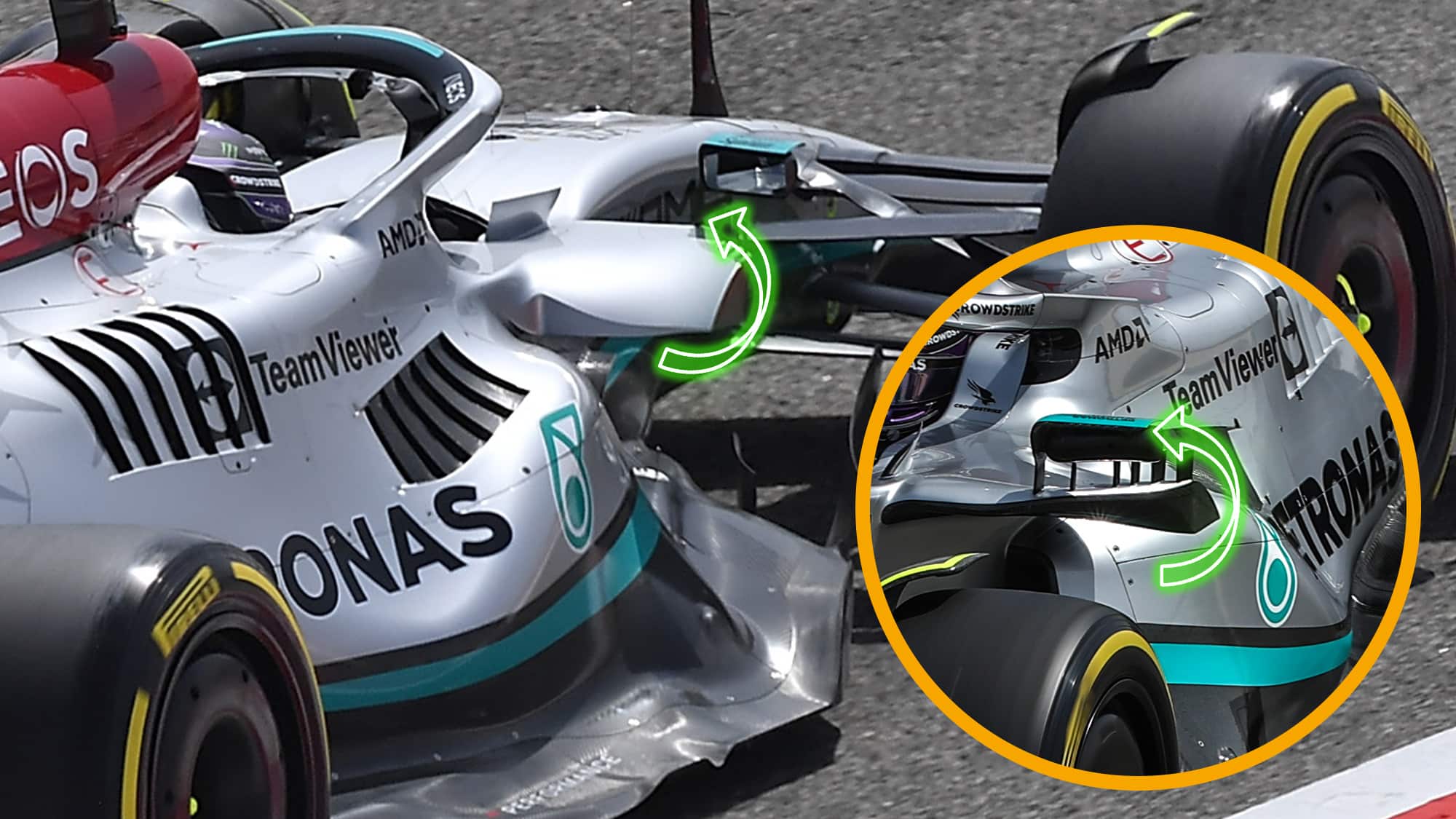
With the legality discussed, lets talk about aerodynamic effects. The desire to put downwashing wings here is nothing new: on the previous set of rules all the cars ran one in one form or another. But let’s talk about why this one is specifically useful here.
Downwash in this region is a positive thing. You get more pressure under the wing, which can help push the turbulent wheel wake out more, and you also force more downwash on the floor leading edge, increasing its suction underneath and reducing losses on the top surface of the floor.
This wing, with its exposed tip, would also have a significant additional benefit, as you would expect it to shed a large and fairly powerful vortex off its edge. This vortex would rotate in such a way that it would push out the mid and lower wake further downstream, as well as draw in what could be relatively high energy air higher up, assuming the upper front wheel vane is doing its job.
This rotation would also encourage outwash along the floor edge, which could help drive extraction from the forward floor — increasing suction through the forward floor — and power up the vortices on the rearwards floor, leading to more suction underneath. This outwash in the forwards portion would be further facilitated by the triangular shape of the sidepod, where any air that was downwashing along it as a result of the SIS wing would be directed fairly well into outwash at the floor curls.
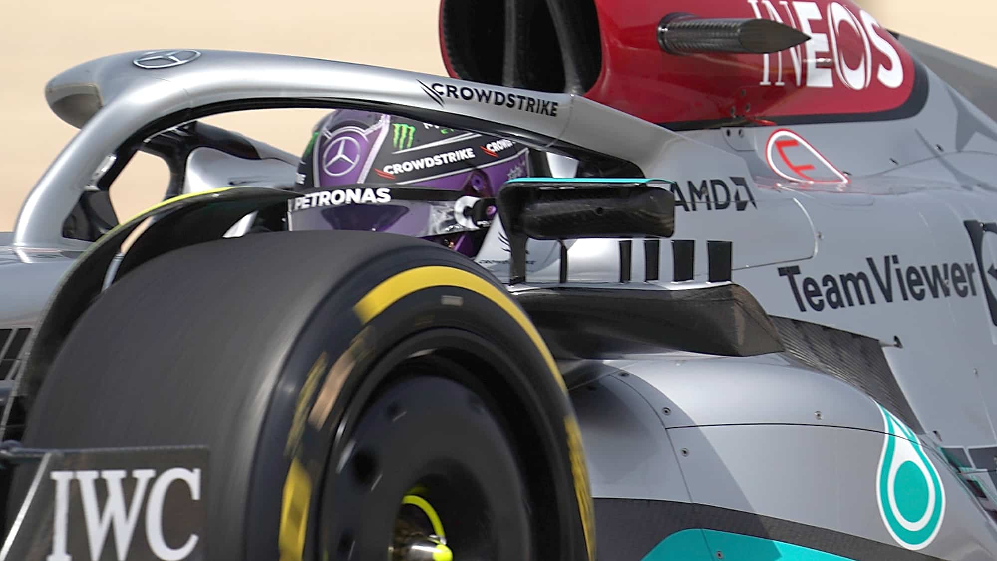
The outwashing mirror stays are working in much the same way as the main SIS wing in terms of the vorticity that they are shedding. This means that they should help power up the overall vorticity of the system (essentially providing a sort of endplating effect), but they also will help to shed the vorticity across multiple shedding edges and depower the vortices shed locally by the SIS wing. This will help clean up the overall vorticity a bit, which should make it more persistent further downstream and keep the flow energy high. Their outwashing nature should also help push all the vortices generated in this region, and potentially a little bit of the upper wake further outboard, and hopefully mean they don’t interfere too much with the quality of the airflow at the beam wing and rear wing.
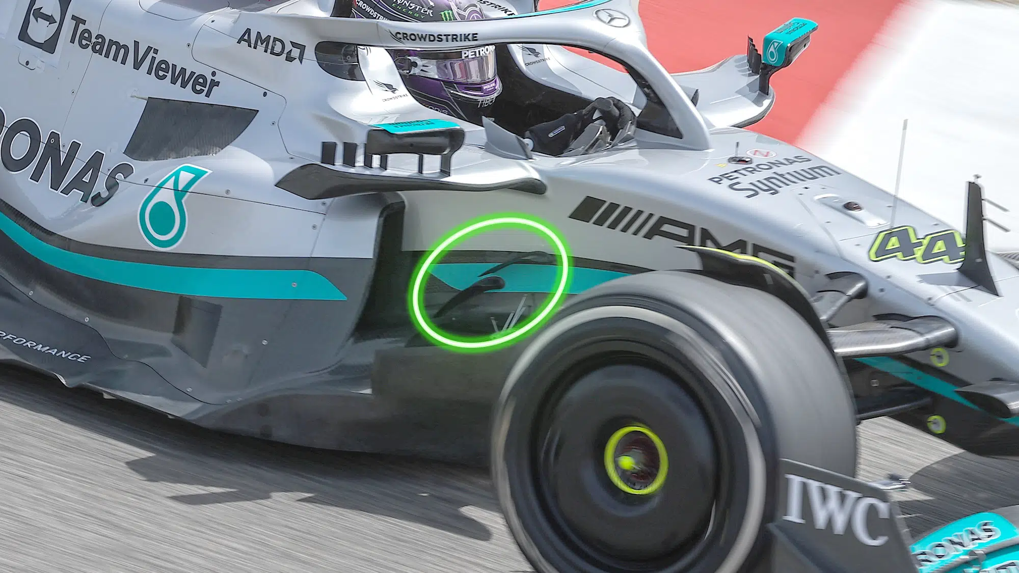
Running that oddly shaped sidpod inlet doesn’t come without cons though – it’s typically harder to get a good air feed for cooling when the bulk of your inlet is just above the floor than when it’s up in free air, and that isn’t helped by how downwashing these floor leading edges are. In addition to that, a tall narrow inlet will suffer more from boundary layer buildup along the side of the chassis, with disturbed air lying between the bodywork and clean airflow. To help control some of the losses introduced by these two things, Mercedes has introduced two downwashing chassis canards in this region. These will create some downwash to supress losses on the top of the floor, and some vorticity to help clean the chassis losses. It’s likely that the vortices produced by these are ingested by the sidepod inlet (not generally a good thing), however Mercedes must have found this to be a better compromise then no flow control at all here.
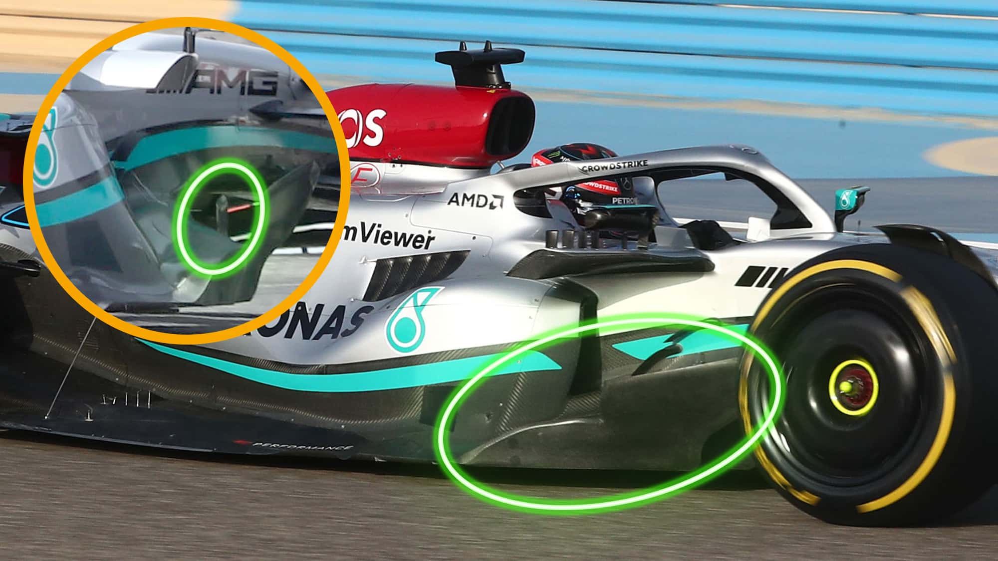
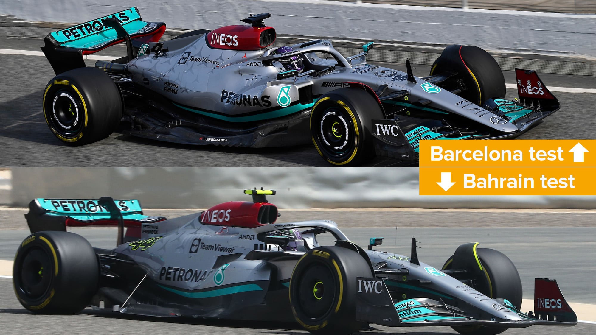
Some other minor development notes: it has ditched the lasagne floor in favour of a more conventional floor curl setup. In a way, this isn’t super surprising – Mercedes did very much the same thing last year. It’s possibly of an indication of extra outwash down low from the SIS wing and new bodywork combo being used to crank this region more effectively
The bargeboard has been tweaked, the upper portion now extends forwards into the legality box, while the lower section stays cut back and caves in further inboard. The top of the most outboard strake has also been extended to become an outwashing vane, while the team elected to keep the two inboard ones low, likely to keep their sidepod inlet as clean as possible.
