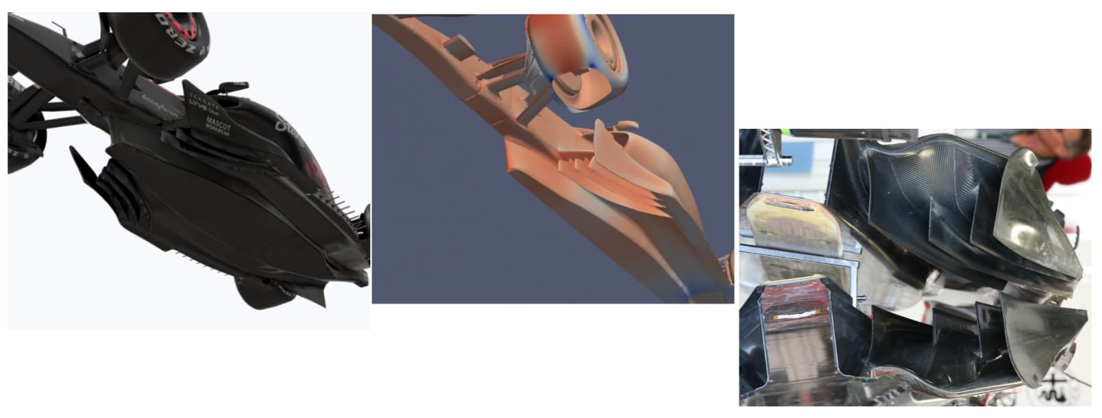
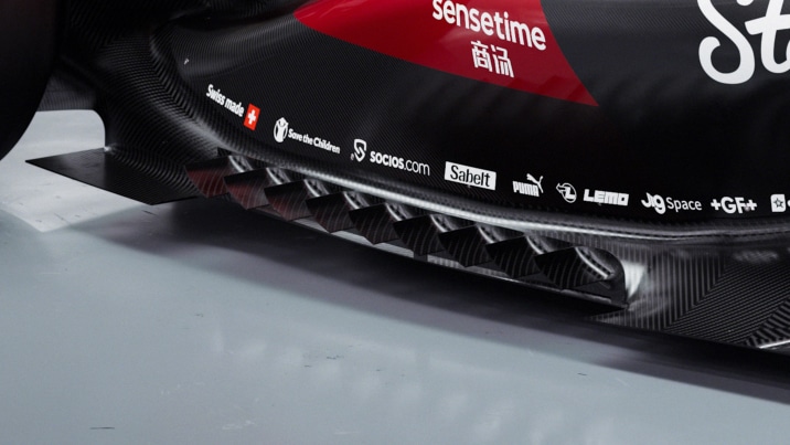
Due to the convex fillet rule, each vane can be no closer than 50mm to another, as otherwise there wouldn’t be enough space to put in a fillet radius of 25mm on each. You also have to have the vanes pretty much dead straight out: you can’t go too fancy with the shapes or you won’t satisfy the section rules.
In terms of what this means – you have essentially 3 choices with this design. You can have straight, flat vanes, with a gap of 50mm between each one. This sacrifices a lot of planform for only the benefit of vortex discretisation and mass flow bleed, where clean air is allowed to pass through the floor edge to ender the underbody, often improving its cleanliness versus an unslotted floor — probably inadvisable.
You can have heavily nose-up vanes – this would be clean but the vanes may be so nose-up that they generate local lift, and may bias the load too much to the inboard floor edge system, which could be undesirable.
Or you could have upwashing vanes, which is what Alfa has here. These upwashing vanes will generate local load and take load off the inboard floor edge vortex system, which will clean it up but they will generate a degree of loss off each one that could be ingested further downstream.
The upwashing system, combined with the vertical fence that they connect to would significantly reduce outwash, and the load on the inboard floor edge, which would locally clean it up, even if the rest of the system might be a bit lossy. You would also discretise the outboard floor edge vortex more, which could help with its health and controllability, although it’s a trade against the losses you introduce by adding more upwash and local load on the vanes, as well as the floor fence.
So why do they have it this year when it was legal last year and anyone could do it? Well, the floor edge is now a fair chunk higher, so perhaps this system now works where perhaps before it didn’t.
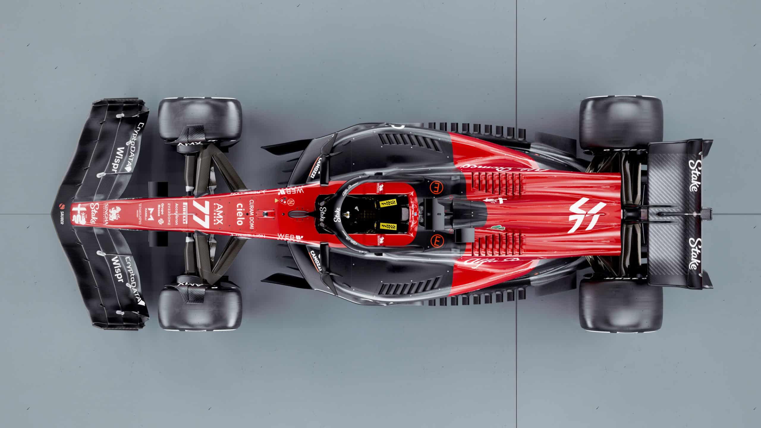
The most notable thing on the rear of the car is the beam wing, with its mildly serrated trailing edge. There’s a lot of research on these types of trailing edges, but it’s mainly centred on noise reduction. This makes sense when you consider an owl’s wing which has a similar detail. Of course, an F1 car doesn’t need to worry about this, so what are we doing here?
When we have a serrated trailing edge on a forwards element, it can produce very small vortices that can help energise the boundary layer of the second element and delay separation. However we are right at the back here.
What trailing edge disturbances like this can help do is break up the shear layer coming off the back of the wing. The air on the top is trying to slide outboard while the air on the bottom is trying to slide inboard. This produces an unstable shear layer of vortex-like structures on the back. By giving the trailing edge some degree of discontinuity you can cast these off as discrete vortices instead of an uncontrolled mess, one of the reasons it works so well for noise suppression with wings at high angles of attack. In terms of what benefit this could give from an aero performance standpoint, this might give a better central wake profile from the losses off the beam wing, potentially a more stable wake with less fluctuations, that could have benefits for downforce or drag. However, I would imagine it’s quite subtle, potentially even neutral.
The other option is this is just something they have added into the launch render for looks — a constant consideration when assessing these pre-launch images!

